
Talk:Audio crossover
| This article is rated B-class on Wikipedia's content assessment scale. It is of interest to the following WikiProjects: | |||||||||||||||||||||
| |||||||||||||||||||||

This page redirects to filters but there is no mention whatsoever of crossovers therein.
Although it seems an appropriate redirect, something should at least exist on the subject before redirection is requested.
- Added contents specific to audio crossovers and filters. This is correct to the best of my knowledge. Please correct if any errors are found, and if possible add more information. Thank you. -- Rohitbd
Thanks Omegatron, for all your efforts in linking and corrections :-) -- Rohitbd
Summed response[edit]
summed response is -6 dB? 0 dB + -80 dB is going to be about 0 dB... — Omegatron 19:42, 23 September 2005 (UTC)
- The summed response of a Bessel or L-R crossover is -6dB relative to the pass-band maximum or -6dB normalised. Rohitbd 22:06, 23 September 2005 (UTC)
- I don't understand why. 1+0.000001 ≈ 1 — Omegatron 03:11, 24 September 2005 (UTC)
- I didn't quite get your question, but if it helps, its -6db because of (1) the filter characteristic, (2) the phase relationship between the signals in the bands and (3) the crossover point is -6db and not -3db. And the summing is not exactly -6dB, VERY slightly lesser (due to loading of the next stage). See this: http://sound.whsites.net/bi-amp.htm#phase_resp and http://sound.whsites.net/project09.htm. All said, maybe the graph is making things harder...should I remove it? -- Rohitbd 06:59, 24 September 2005 (UTC)
- Changed the related text to make it clearer. Rohitbd 07:12, 24 September 2005 (UTC)
- I don't understand why. 1+0.000001 ≈ 1 — Omegatron 03:11, 24 September 2005 (UTC)
- Well, there are two filters. A lowpass and a highpass. Right? Each has unity gain in the passband. So whatever signal you put in in the passband comes out almost exactly the same level. Then the two waveforms sum in the air which gives the overall summed response, right? The passband of one filter corresponds to the stopband of the other, which is a much lower level. Even if the phases cancel, the magnitude of the stopband is so much smaller that the summed response will be close to unity gain everywhere, not -6 dB. If the -6 dB comes from loading or something that isn't taken into account in the filter output, then that might make sense. — Omegatron 22:36, 24 September 2005 (UTC)
- Omegatron, most of what you say is true, and perhaps the confusion is because of my implicit assumption - the summing shown is electrical and not acoustic because it is far easier to measure electrical summing and it follows that the acoustic summing must also be a function of the electrical summing. That said, IMHO, we cannot assume that since the stopband of one corresponds to the passband of the other the summing should be closer to unity (0db) - this is more applicable to filters with a very sharp knee and extremely steep slopes. With Bessel or L-R, the slope starts out much shallower than Butterworth - if you compare the (real) graphs of both, you will see that the Bessel or L-R has a softer "knee" than Butterworth. At this point, I must confess that I do not know the mathematics behind it - what I wrote is based on the material provided in the references section, and perhaps it needs re-wording. Further, what I have written is more to explain why a Butterworth is not preferable and not why the summing is at −6dB.
- Rohitbd 10:40, 25 September 2005 (UTC)
- Well, there are two filters. A lowpass and a highpass. Right? Each has unity gain in the passband. So whatever signal you put in in the passband comes out almost exactly the same level. Then the two waveforms sum in the air which gives the overall summed response, right? The passband of one filter corresponds to the stopband of the other, which is a much lower level. Even if the phases cancel, the magnitude of the stopband is so much smaller that the summed response will be close to unity gain everywhere, not -6 dB. If the -6 dB comes from loading or something that isn't taken into account in the filter output, then that might make sense. — Omegatron 22:36, 24 September 2005 (UTC)
- Hmmmm... :-) — Omegatron 20:41, 15 October 2005 (UTC)
- That's not correct in the electrical world either man.... Electrically, it's the sum of the complex responses. The only way you add dB values is if you are MULTIPLYING two responses together. dB = 20log[X] hence 20log[XY] = 20log[X] + 20log[Y] = dB1 + dB2. 20log[X+Y] has no simple formula like that. Rather you have to compute the complex valued response which is mag*cos(phase) + i*mag*sin(phase) then add back together. User:Kaeding/sig 3:02, 6 December 2005 (UTC)
- PHASE. That's it! Now how could I have overlooked it? It is the phase relationship between the filter sections that results in flat summing with a Bessel or L-R crossover. Rohitbd 16:22, 20 February 2006 (UTC)
- That's not correct in the electrical world either man.... Electrically, it's the sum of the complex responses. The only way you add dB values is if you are MULTIPLYING two responses together. dB = 20log[X] hence 20log[XY] = 20log[X] + 20log[Y] = dB1 + dB2. 20log[X+Y] has no simple formula like that. Rather you have to compute the complex valued response which is mag*cos(phase) + i*mag*sin(phase) then add back together. User:Kaeding/sig 3:02, 6 December 2005 (UTC)
- So, after all the mathematical mumbo-jumbo, the summed response of a crossover IS or IS NOT ~6db below the passband level? At least in active crossovers that sum flat, it seems impossible that the summed response could be down 6db in any practical device. Why? Because the contribution of the high-pass section to the response of the low-pass section at, say, 4 octaves below the crossover point would be so minimal in amplitude that even if it were 180 degrees out of phase with the low -pass signal it would not seem to be able to pull the low-pass signal down 6db at that point. The same would seem to be true for the effect of the low-pass section with respect to the high-pass response 4 octaves higher than the crossover point. Also, I've read a lot of literature on the amplitude and phase response of active crossovers and I've never seen a graph showing the summed response to be 6db below the passband level. Is it different with passive crossovers? What am I missing here? Anoneditor 03:54, 27 April 2006 (UTC)
Yes, the electrical summing is 6dB lower than the pass-band maxima. An ideal passive crossover (one that is immune to the driver's parameters and doesn't have insertion loss) will exhibit exactly the same electrical summing as an active crossover. However, it should be noted that the crossover's outputs are not meant to be summed electrically for normal use - the electrical summing is done solely to determine or verify that the combined response is flat (the -6dB summing is simply a result of the filters' characteristics and interactions with each other), an active crossover's outputs are connected to individual amplifiers which in turn are connected to speaker drivers; and a passive crossover's outputs are connected to speaker drivers. So as far as the load connected to each output of the crossover goes, each will see the respective input unattenuated if it is within the particular filter's pass-band. That said, the electrical summing is only important as far as the crossover points go - if the electrical summing is not flat (i.e, dips/peaks at crossover points) the acoustic summing to won't be flat either. Rohitbd 09:42, 5 May 2006 (UTC)
- Added clarifications to the article to alleviate any confusion arising out of the way the electrical summing is depicted. Rohitbd 11:34, 6 May 2006 (UTC)
- Removed the confusing portion about electrical summing at -6dB. However, what matters is that the crossover sums flat electrically or acoustically, and the -6dB electrical summing is not of significance as far as the article goes. Rohitbd 16:20, 6 May 2006 (UTC)
Thank you for your response, Rohitbd. Let me restate what I understanding of what you are saying just to make sure that I am not confused. You are asserting that the summed electrical response of a two-pole Bessel crossover is 6 dB below the amplitude of the passband of both the high and low pass filters that make up that crossover. So, for example, if the crossover frequency is 2 kHz, then the summed response would be 6 dB below the input at 250 Hz, 500 Hz, 1 kHz, 4 kHz, 8 kHz and 16 kHz. Is this correct? If so, at the risk of becoming a pest, would you please tell me the mechanism for such a passband amplitude reduction? I’m asking because it seems to me that at 250 Hz, for example, even if a high-pass output were 180 deg. out of phase with the low-pass output at that frequency, the sum could not be 6 dB below the low pass passband because the high pass output at that frequency is 36 dB down (1/8 the amplitude).
Let me add that I’ve never seen your assertion before. Every other graph of summed electrical response for two-pole Bessel crossovers I’ve come across shows no such 6 dB reduction. See, e.g., Vance Dickason, The Loudspeaker Design Cookbook, 5th Ed. (Audio Amateur Press 1997) p. 98, showing the summed response of the vast majority of audio crossover networks; and Figs. 3 and 4 shown in http://www.rane.com/note147.html by the Rane Corporation, a crossover manufacturer in the U.S.
I will greatly appreciate hearing from you. Anoneditor 18:04, 11 May 2006 (UTC)
- If you tie the outputs of a crossover using resistors and measure the summed output it will always show 6dB attenuation - unfortunately I happened to mention this as "summing flat" where it should have been avoided in the first place. The 6dB reduction is always present with passive resistive summing. I should have realised this earlier - my mistake and I have corrected it in the article. However user Ron E has already made some sweeping changes to the article so it shouldn't cause any confusion to readers now. Rohitbd 07:46, 12 May 2006 (UTC)
Bessel is not L-R[edit]
It seems that there's a little confusion here. AFAIK Bessel filters don't have a -6dB gain at cutoff, and their sum is not flat, it has a little dip instead. The -6dB cutoff freq and flat summed response is the characteristic of Linkwitz-Riley filters. Refer to: http://www.rane.com/note147.html scoofy 10:18, 7 May 2006 (UTC) (those wishing to explore deeper details of the math can refer tothe personal page of Mr. Linkwitz himself! http://www.linkwitzlab.com )
- The sallen-key unity gain filter has a Q of 0.5 and this is LR2...however Bessel filters also have a Q of 0.5... Rohitbd 12:34, 7 May 2006 (UTC)
- You're wrong. Bessel filter has a Q of approximately 0.58. References:Active Lowpass Filter Design (look at Table 2.), Another reference Third reference Fourth reference . This page says Bessel filters have a Q factor of 0.5 to 0.7, with a remark that a 'true' Bessel filter has a Q of 0.57. So we might say that a filter with a Q of 0.5 is a Bessel-like filter. You're right in the sense that the LR filter has a character very similar to the Bessel character, which have almost the same gain at and the sum of the outputs is also nearly flat, and both filters are linear phase in the passband. Regards scoofy 12:56, 7 May 2006 (UTC)
- Yes, I did mix up LR2 & Bessel - I have made this change in the article. Rohitbd 08:25, 8 May 2006 (UTC)
- I think, we should not confuse LR2 with Bessel. A Bessel filter is a filter with a transfer function H(s)=K0/Ben(s/ω0), where Ben is the nth Bessel polynomial, meaning that a 2nd order Bessel filter has a transfer function H(s)=3/((s^2)+3s+3) (reference1) (reference2), which can be realized by a two pole filter with a Q of 0.577. This, and only this is a Bessel filter, anything else is not a Bessel filter, in the strictest sense. Besides this, a common definiton found on the net (which may be the source of confusion) is that a Bessel filter is filter with a linear phase resonse and a constant group delay. However, this is only partially true, Bessel filters are filters which at the same time have the maximally flat amplitude response retaining a linear phase response and a constant group delay. (ref) This is not true of LR2 filters, which have a softer "knee" at the cutoff frequency. I suggest that we don't mix up these two, because this is an encyclopedia, and many people will use it as a reference, so we shouldn't include an information that is not true. (Of course, we can include a remark that in common practice, sometimes all linear phase filters are called Bessel filters, but we shouldn't mix them up in the article.) It is also a very wrong idea to say that a filter with a Q of 0.7 is a Bessel filter, because practically it is a a Butterworth filter (Butterworths have a Q of 0.707), so it doesn't have any of the typical Bessel character (it has a peak in the group delay, it's phase response is non-linear). Regarding the peak/dip question: The summed output of the Bessel filters can have a peak, a dip or a ripple depending on how you mix the two, whether you invert the phase of one output or not, and what kind of frequency normalization you use. Normalisation means you scale the cutoff frequency of the filters by a certain factor, so the cutoff freq of the LP and HP filter gets closer or further from each other. Possible summed outputs can look like: graph1 graph2 graph3 graph4. The last graph shows what happens if you use different normalisation values, which can be shown on a 3d graph: graph5. Probably the "phase match" graph is the most appropriate regarding crossovers, which - truly - has a dip. You should note that none of these graphs look flat, which is another reason not to say this graph depicts a Bessel filter. Regards scoofy 11:00, 9 May 2006 (UTC)
- Yes, differentiation should be made between generalised bessel, true bessel & LR types, but going into too much detail may be counter-productive especially since the filters have their own articles and the links in the references section should provide ample material for those who want to delve deeper into it. I would also recommend some simplification/shortening of the article where we just touch on the filters (Butterworth/Bessel/LR and link to the respective articles) and give a brief account of their salient characteristics from the point-of-view of use in audio and leave it at that. Rohitbd 11:15, 9 May 2006 (UTC)
- Agree with that. I'll look at it later and think of how could it be reorganized. scoofy 11:42, 9 May 2006 (UTC)
- Reorganized article. Removed Classification by filter type, put the relevant information into the appropriate sections. Also moved a lot of stuff from the Overview. I think the Overview is still a little bit fuzzy, we could possibly have an overview where first: we discuss what does a crossover network consist of (lowpass & highpass filters) (not going into details about filters and filter characteristics) and then second: get some overall info on filter characteristics and what kind of filters are best as crossovers. I think some info could be moved to the latter sections (eg info on 2nd order Butterworth filters could be moved tho the Second order crossovers section. Probably this would clean up the article a little bit. scoofy 23:20, 9 May 2006 (UTC)
- Thanks Scoofy for all your efforts, it is highly appreciated !! :-) Rohitbd 08:32, 10 May 2006 (UTC)
- Yes, differentiation should be made between generalised bessel, true bessel & LR types, but going into too much detail may be counter-productive especially since the filters have their own articles and the links in the references section should provide ample material for those who want to delve deeper into it. I would also recommend some simplification/shortening of the article where we just touch on the filters (Butterworth/Bessel/LR and link to the respective articles) and give a brief account of their salient characteristics from the point-of-view of use in audio and leave it at that. Rohitbd 11:15, 9 May 2006 (UTC)
- I think, we should not confuse LR2 with Bessel. A Bessel filter is a filter with a transfer function H(s)=K0/Ben(s/ω0), where Ben is the nth Bessel polynomial, meaning that a 2nd order Bessel filter has a transfer function H(s)=3/((s^2)+3s+3) (reference1) (reference2), which can be realized by a two pole filter with a Q of 0.577. This, and only this is a Bessel filter, anything else is not a Bessel filter, in the strictest sense. Besides this, a common definiton found on the net (which may be the source of confusion) is that a Bessel filter is filter with a linear phase resonse and a constant group delay. However, this is only partially true, Bessel filters are filters which at the same time have the maximally flat amplitude response retaining a linear phase response and a constant group delay. (ref) This is not true of LR2 filters, which have a softer "knee" at the cutoff frequency. I suggest that we don't mix up these two, because this is an encyclopedia, and many people will use it as a reference, so we shouldn't include an information that is not true. (Of course, we can include a remark that in common practice, sometimes all linear phase filters are called Bessel filters, but we shouldn't mix them up in the article.) It is also a very wrong idea to say that a filter with a Q of 0.7 is a Bessel filter, because practically it is a a Butterworth filter (Butterworths have a Q of 0.707), so it doesn't have any of the typical Bessel character (it has a peak in the group delay, it's phase response is non-linear). Regarding the peak/dip question: The summed output of the Bessel filters can have a peak, a dip or a ripple depending on how you mix the two, whether you invert the phase of one output or not, and what kind of frequency normalization you use. Normalisation means you scale the cutoff frequency of the filters by a certain factor, so the cutoff freq of the LP and HP filter gets closer or further from each other. Possible summed outputs can look like: graph1 graph2 graph3 graph4. The last graph shows what happens if you use different normalisation values, which can be shown on a 3d graph: graph5. Probably the "phase match" graph is the most appropriate regarding crossovers, which - truly - has a dip. You should note that none of these graphs look flat, which is another reason not to say this graph depicts a Bessel filter. Regards scoofy 11:00, 9 May 2006 (UTC)
- Yes, I did mix up LR2 & Bessel - I have made this change in the article. Rohitbd 08:25, 8 May 2006 (UTC)
- You're wrong. Bessel filter has a Q of approximately 0.58. References:Active Lowpass Filter Design (look at Table 2.), Another reference Third reference Fourth reference . This page says Bessel filters have a Q factor of 0.5 to 0.7, with a remark that a 'true' Bessel filter has a Q of 0.57. So we might say that a filter with a Q of 0.5 is a Bessel-like filter. You're right in the sense that the LR filter has a character very similar to the Bessel character, which have almost the same gain at and the sum of the outputs is also nearly flat, and both filters are linear phase in the passband. Regards scoofy 12:56, 7 May 2006 (UTC)
SVG image does not appear correcty[edit]
I uploaded an SVG image of a comparison of Butterworh and L-R crossovers, which does not appear correctly. However, when I download the imageit appears correctly in my browser. Any suggestions? scoofy 11:33, 7 May 2006 (UTC)
- Even I cannot see it. Perhaps changing the format to GIF/PNG will work. Rohitbd 12:37, 7 May 2006 (UTC)
- I uploaded it in PNG. It is fine now.scoofy 13:20, 7 May 2006 (UTC)
The actual acoustic slope achieved is a combination of the filter slopes of the driver and that of its filter section[edit]
User:Ron E wrote: The actual acoustic slope achieved is a combination of the filter slopes of the driver and that of its filter section. AFAIK a driver does not have a filter section (actually, the crossover itself is the filter). Probably he meant that a driver itself has a certain frequency response curve, which interacts with the crossover filter's slope, thus the final slope is steeper than the slope of the filter itself alone. (The combination of both the natural characteristics of the drivers and the electrical filtering produces the acoustic slope. source) Corrected it.scoofy 02:18, 13 May 2006 (UTC)
- look at it rather as: The actual acoustic slope achieved is a combination of the rolloff slopes of the driver and that of its filter section--Ron E 04:19, 13 May 2006 (UTC)
- Wait!! The above condition is not the best way to get a crossover - first of all a crossover built using a 12db/oct electrical filter and the drivers' responses will be too much dependent on driver characteristics to be of any use. This is not to say that it is not used, but generally we try to keep the crossover slope as independent of the drivers as possible. For example, with a 12dB/oct crossover if we want to cross over at 1kHz, then the woofer MUST have a HF response that extends atleast upto 2kHz and the tweeter MUST have a LF response that extends atleast down to 600-700Hz. If the drivers do not satisfy the above requirement then a 24db/oct or higher order crossover is needed. In the above case, if the woofer and tweeter both have a -3db of 1.5kHz (a condition seldom met in practice), a 12db/oct electrical crossover (of 1.5kHz) will give a combined crossover slope of 18db/oct - the woofer/tweeter will cut at approx. 6db/oct. The above method is used ONLY if the drivers have extremely controlled slopes and that at the extremities of their individual freq. responses they can operate with good directivity (esp. the woofer which must not have any "cone-breakup" or lobing at the HF end). Rohitbd 07:38, 13 May 2006 (UTC)
- Rohitbd, this is the way crossovers are designed. One has to consider driver response as part of the package. If you investigate well-designed systems on the internet (where much of your information seems to come), you will find essentially none (except those designed by rank beginners) that use an actual L-R or Bessel or Butterworth circuit. What is generally done is to formulate a target response based on L-R (or Butterworth...) transfer function coefficients, and design a circuit which causes the driver to take on that target response. This is done with Zoebels and notch or contour filters as well as other response shaping circuits. Allowance must be given for the noncoincident arrangement of the drivers and their relative phase at the crossover frequency. While you were quick to add back the information about phase and inverted driver polarity, it is really not correct in the general sense. It would only apply if the drivers were perfect transducers, having perfectly flat frequency response from DC to (nearly) infinite frequency, such that their phase response matched perfectly and there was no driver response to worry about.--Ron E 18:37, 13 May 2006 (UTC)
- Yes, a notch filter, a contour circuit, zobel (the correct term for speaker drivers is impedance equaliser), etc are used to make the final acoustic response as flat as possible - BUT these are not part of the crossover. If you see the Linkwitz website you will see that the crossovers are LR and notch, contour, time-alignment ckts are added to bring the acoustic response in line with the crossover summing. The crossover is still independent of the drivers. A notch or peak is usually when a driver is reaching its -3dB point - the crossover doesn't care about it, as its taken care of by the contour circuit. Rohitbd 08:09, 14 May 2006 (UTC)
- I notice you have a tendency to attempt to define terms. In that vein, a crossover is merely an audio filter which is used to shape the response of a loudspeaker. Notches and contour networks and zoebels (zoebels are actually more generally called impedance conjugate networks - can you explain why?) are merely added filter elements and are thus by definition part of the crossover as a whole. Maybe if you can explain what you mean by: "...bring the acoustic response in line with the crossover summing. The crossover is still independent of the drivers. A notch or peak is usually when a driver is reaching its -3dB point - the crossover doesn't care about it, as its taken care of by the contour circuit.", I can address those misconceptions as well. If the crossover were independent of the drivers, one would not need to know the driver impedance or frequency response in designing them. A notch or peak can actually occur anywhere and has nothing to do with "-3dB", etc....Ron E 02:53, 20 May 2006 (UTC)
- Well Ron, I am only using standard terms here - an audio crossover "proper" is an entity separate from the contour networks and it is not a device to shape a speaker's response. The impedance conjugate networks (zobel network) are basically meant as a "sit-in" (so to speak) between the passive crossover and the driver so that the crossover sees a loading that is largely resistive - note that crossovers are designed for a particular load impedance and this impedance is a single value at a given frequency and not the variable impedance of the driver. In fact many crossovers are simply designed by measuring the driver's impedance at the crossover frequency without bothering about the impedance at other frequencies. This is not ideal, but it works. Impedance correction networks will simply act to make the driver appear as a resistive load to the crossover, so that the crossover can work correctly at other frequencies too - the acoustic effect may be debatable though.
- I notice you have a tendency to attempt to define terms. In that vein, a crossover is merely an audio filter which is used to shape the response of a loudspeaker. Notches and contour networks and zoebels (zoebels are actually more generally called impedance conjugate networks - can you explain why?) are merely added filter elements and are thus by definition part of the crossover as a whole. Maybe if you can explain what you mean by: "...bring the acoustic response in line with the crossover summing. The crossover is still independent of the drivers. A notch or peak is usually when a driver is reaching its -3dB point - the crossover doesn't care about it, as its taken care of by the contour circuit.", I can address those misconceptions as well. If the crossover were independent of the drivers, one would not need to know the driver impedance or frequency response in designing them. A notch or peak can actually occur anywhere and has nothing to do with "-3dB", etc....Ron E 02:53, 20 May 2006 (UTC)
- Yes, a notch filter, a contour circuit, zobel (the correct term for speaker drivers is impedance equaliser), etc are used to make the final acoustic response as flat as possible - BUT these are not part of the crossover. If you see the Linkwitz website you will see that the crossovers are LR and notch, contour, time-alignment ckts are added to bring the acoustic response in line with the crossover summing. The crossover is still independent of the drivers. A notch or peak is usually when a driver is reaching its -3dB point - the crossover doesn't care about it, as its taken care of by the contour circuit. Rohitbd 08:09, 14 May 2006 (UTC)
- Rohitbd, this is the way crossovers are designed. One has to consider driver response as part of the package. If you investigate well-designed systems on the internet (where much of your information seems to come), you will find essentially none (except those designed by rank beginners) that use an actual L-R or Bessel or Butterworth circuit. What is generally done is to formulate a target response based on L-R (or Butterworth...) transfer function coefficients, and design a circuit which causes the driver to take on that target response. This is done with Zoebels and notch or contour filters as well as other response shaping circuits. Allowance must be given for the noncoincident arrangement of the drivers and their relative phase at the crossover frequency. While you were quick to add back the information about phase and inverted driver polarity, it is really not correct in the general sense. It would only apply if the drivers were perfect transducers, having perfectly flat frequency response from DC to (nearly) infinite frequency, such that their phase response matched perfectly and there was no driver response to worry about.--Ron E 18:37, 13 May 2006 (UTC)
- Wait!! The above condition is not the best way to get a crossover - first of all a crossover built using a 12db/oct electrical filter and the drivers' responses will be too much dependent on driver characteristics to be of any use. This is not to say that it is not used, but generally we try to keep the crossover slope as independent of the drivers as possible. For example, with a 12dB/oct crossover if we want to cross over at 1kHz, then the woofer MUST have a HF response that extends atleast upto 2kHz and the tweeter MUST have a LF response that extends atleast down to 600-700Hz. If the drivers do not satisfy the above requirement then a 24db/oct or higher order crossover is needed. In the above case, if the woofer and tweeter both have a -3db of 1.5kHz (a condition seldom met in practice), a 12db/oct electrical crossover (of 1.5kHz) will give a combined crossover slope of 18db/oct - the woofer/tweeter will cut at approx. 6db/oct. The above method is used ONLY if the drivers have extremely controlled slopes and that at the extremities of their individual freq. responses they can operate with good directivity (esp. the woofer which must not have any "cone-breakup" or lobing at the HF end). Rohitbd 07:38, 13 May 2006 (UTC)
- As for "bringing the acoustic network in line with the crossover" - all it means is that the speaker's acoustic output is corrected for dips/peaks by using extra circuitry - the impedance equaliser is just one such in the scheme of things - the impedance equaliser makes the driver appear resistive to the crossover and the contour network simply corrects for peaks/dips - yes using it will affect the crossover too, but if the final acoustic response if satisfactory then this shouldn't be an issue. You term all these as part of the crossover while I term them as separate - as do many more people, see this, figures 3.3, 3.6 (impedance correction); the article clearly demostrates that the crossover is designed after the impedance has been corrected. For contour networks, you can always refer to any speaker design book (David B. Weems, for example). Rohitbd 09:43, 22 May 2006 (UTC)
- The problem with your understanding of this topic is that it is superficial. As clearly demonstrated by your responses to the -6dB comments above, your concept of "proper" terminology is limited. Your statements above about designing crossovers using single frequency impedance measurements and not using the actual driver complex impedance merely underlines your inexperience and lack of understanding on this topic. Weems writes to such an audience, as do most webpages on the topic. Since you mention him explicitly, take a look at his crossover designs and see how many of them are determined solely by the kind of cookbook methods you are describing, and which he ironically promotes in his book. BTW, an impedance conjugate network is so named because its impedance (in theory, but not actually) is the complex conjugate of the inductive rise of the woofer. If you look at conjugate networks used in common loudspeakers designed by professionals, you will find they differ (more often than not) from the values that merely flatten impedance, and not just because the impedance rise of speakers is not purely inductive. Imagine a first order lowpass filter with an RC impedance conjugate, then progressively reduce the resistor value in the conjugate - when does it become a 2nd order filter? Conjugate networks (and notch filters) are used as additional response shaping elements - which places them solidly in the crossover arena. Neville Thiele has recently published on a "new" type of crossover which an amateur might interpret as a crossover with a "separate" ;-) notch filter. In truth, it is a family of filters with zeroes in the transfer function. Oh, and they sum flat, and not to -6dB.....Ron E 03:21, 25 May 2006 (UTC)
- If you have so much confidence about what you are saying, go ahead and change it instead of wasting your time arguing with an inexperienced, amatuer like me. But be aware that if it goes against what is written in books and web pages (for audiences who lack experience and understanding - according to you), it will be reverted by inexperienced amatuers who happen to see the article. I do agree that I got the -6db summing wrong - that's because passive resistive summing always results in 6db loss, and I had assumed this model to be valid for checking flatness of summing. So, please contribute to the article instead of analysing me or my understanding. Or better still, analyse yourself :-). And oh, you may wish to read these: Wikipedia:Etiquette & Wikipedia:No_personal_attacks - saying things like "The problem with your understanding of..." or "...merely underlines your inexperience and lack of understanding...", and so on are just at (if not beyond) the boundary of breaking certain wikipedia norms. Rohitbd 13:27, 25 May 2006 (UTC)
- The problem with your understanding of this topic is that it is superficial. As clearly demonstrated by your responses to the -6dB comments above, your concept of "proper" terminology is limited. Your statements above about designing crossovers using single frequency impedance measurements and not using the actual driver complex impedance merely underlines your inexperience and lack of understanding on this topic. Weems writes to such an audience, as do most webpages on the topic. Since you mention him explicitly, take a look at his crossover designs and see how many of them are determined solely by the kind of cookbook methods you are describing, and which he ironically promotes in his book. BTW, an impedance conjugate network is so named because its impedance (in theory, but not actually) is the complex conjugate of the inductive rise of the woofer. If you look at conjugate networks used in common loudspeakers designed by professionals, you will find they differ (more often than not) from the values that merely flatten impedance, and not just because the impedance rise of speakers is not purely inductive. Imagine a first order lowpass filter with an RC impedance conjugate, then progressively reduce the resistor value in the conjugate - when does it become a 2nd order filter? Conjugate networks (and notch filters) are used as additional response shaping elements - which places them solidly in the crossover arena. Neville Thiele has recently published on a "new" type of crossover which an amateur might interpret as a crossover with a "separate" ;-) notch filter. In truth, it is a family of filters with zeroes in the transfer function. Oh, and they sum flat, and not to -6dB.....Ron E 03:21, 25 May 2006 (UTC)
- As for "bringing the acoustic network in line with the crossover" - all it means is that the speaker's acoustic output is corrected for dips/peaks by using extra circuitry - the impedance equaliser is just one such in the scheme of things - the impedance equaliser makes the driver appear resistive to the crossover and the contour network simply corrects for peaks/dips - yes using it will affect the crossover too, but if the final acoustic response if satisfactory then this shouldn't be an issue. You term all these as part of the crossover while I term them as separate - as do many more people, see this, figures 3.3, 3.6 (impedance correction); the article clearly demostrates that the crossover is designed after the impedance has been corrected. For contour networks, you can always refer to any speaker design book (David B. Weems, for example). Rohitbd 09:43, 22 May 2006 (UTC)
- Ron E: I thought you mean that, but the wording you used (filter slopes of the driver) looked odd to me. Do you call the natural response of the driver filter slope? I'm just asking because I haven't heard it like this before, but well, to an extent, the driver's response is similar to a filter's response (however this may sound misleading, because the driver does not have a filter circuit, that's why I changed it).scoofy 10:11, 13 May 2006 (UTC)
- No, scoofy, you were correct to change it. I was thinking that way when writing because it is a convenient way of representing driver response - the response of the filtered driver then being the cascade (multiple) of driver response and filter response. I was making a lot of changes and rearrangements (the article has really needed it for some time) and I didn't read it with a fresh eye before saving. As to your section on Another use..., I removed it because it really refers to other types of audio filters and signal processors and not specifically to audio crossovers, perhaps it needs its own article?--Ron E 18:37, 13 May 2006 (UTC)
- Yep, the article is much better after this rearrangement, we have been talking about the need or reorganisation with Rohitbd. The Another use... section refers to the same types of audio filters , with the only difference that they are used in differnt kinds of signal processors rather than loudspeakers. However, both the theory and the actual realization is roughly the same as in loudspeakers (except that there's no driver response to be considered). For example the Dolby noise reduction system first used Butterworth filters, then they moved to Bessel; multiband signal processing programs sometimes use digital approximations of Linkwitz-Riley filters, etc. So if the Audio crossovers article is not to be about audio crossovers in loudspeakers, but audio crossvers in general, then they are perfectly appropriate to mention. However, I agree that all this topic is worth a separate article, my suggested name for the article is multiband processing. scoofy 16:44, 14 May 2006 (UTC)
- No, scoofy, you were correct to change it. I was thinking that way when writing because it is a convenient way of representing driver response - the response of the filtered driver then being the cascade (multiple) of driver response and filter response. I was making a lot of changes and rearrangements (the article has really needed it for some time) and I didn't read it with a fresh eye before saving. As to your section on Another use..., I removed it because it really refers to other types of audio filters and signal processors and not specifically to audio crossovers, perhaps it needs its own article?--Ron E 18:37, 13 May 2006 (UTC)
At the end of "Classification based on the number of filter sections," there is an italicized sentence that says, "Remark: Filter sections mentioned here is not to be confused with the individual 2-pole filter sections that a higher order filter consists of." I guess I understand what it is trying to say, but I don't understand its relevance given the remainder of the text. In any event, it is ungrammitical and if it is still relevant, it probably should be changed to read: "Remark: Filter sections mentioned here are not to be confused with the individual 2-pole filter sections of which higher order filters consist." Anoneditor 04:35, 8 November 2006 (UTC)
Error in Active Crossover Section?[edit]
I'm by no means an expert in this area, but this statement strikes me as incorrect (or at the very least, misleading):
- This means that an active crossover based system will often cost more than a passive crossover based system, although no one of the amplifiers needs to provide as high an output as a single full-frequency, power amplifier.
Isn't it true that the vast majority of power consumed by a loudspeaker is in the reproduction of low frequencies? If so, it seems to me that this statement is more or less incorrect.
Think about it this way...you have one loudspeaker with a passive crossover powered by a 120W amp. 99% of the power is consumed by the woofers while less than 1% of the power is consumed by the tweeter. If you were to replace the passive crossover with an active crossover containing two amplifiers, the low frequency amp would have to very, very close to 120W...so close it may as well be a 120W amp.
Yes? No? Do I have this totally wrong?
- I think the statement in the article is technically correct and that you are more or less correct in a practical way, if you restrict the fact situation to your example, which implies a loud bass signal compared to the remainder of the musical program. However, in other situations, there may be no comparatively large bass component in the signal. In such cases, the ratio of power consumed between the woofer and, say, the mid range speaker will be more equal. Anoneditor 16:58, 31 January 2007 (UTC)
Passive Crossovers[edit]
I deleted the last paragraph of this section (as of April 4) for two reasons:
- First, it offers a point of view that is highly disputed in audiophile circles, i.e. that passive crossovers are preferred. In fact, the author's recounting of how difficult it is to properly mate a passive crossover to a specific speaker testifies against the practicality of the notion.
- Second, I think it's wrong in its statement that it is impossible for an active Butterworth filter to be designed without ripple. What's the source for this statement? Also, why does the author believe that in practice it is possible to create a passive Butterworth crossover that hits the theoretical transfer function exactly. This seems problematical given the inevitable component and measurement tolerances and the problem of mating the crossover to the speaker? Anoneditor 23:37, 4 April 2007 (UTC)
- Theoretically, odd order Butterworth filters (no matter active or passive) sum flat without any ripple. For this reason, 3rd order Butterworth is used in crossovers. For even orders, flat summing is problematic, so L-R is preferred. scoofy 14:36, 7 April 2007 (UTC)
Filter Comparsion[edit]
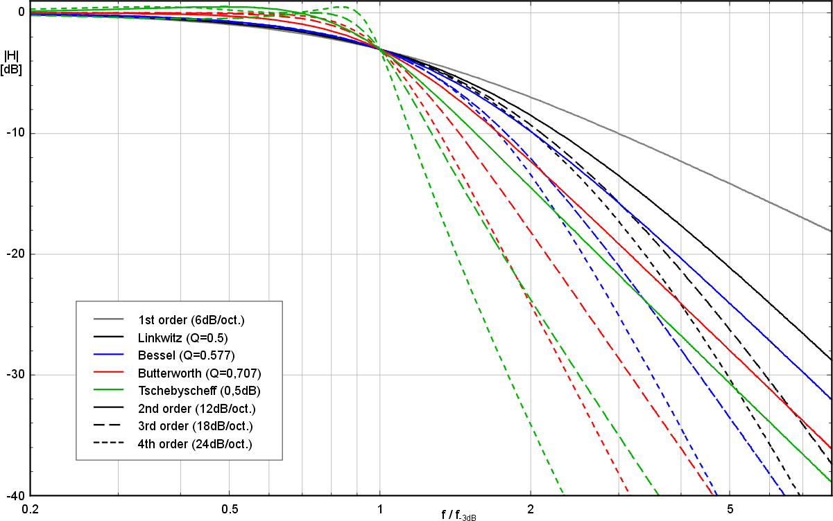
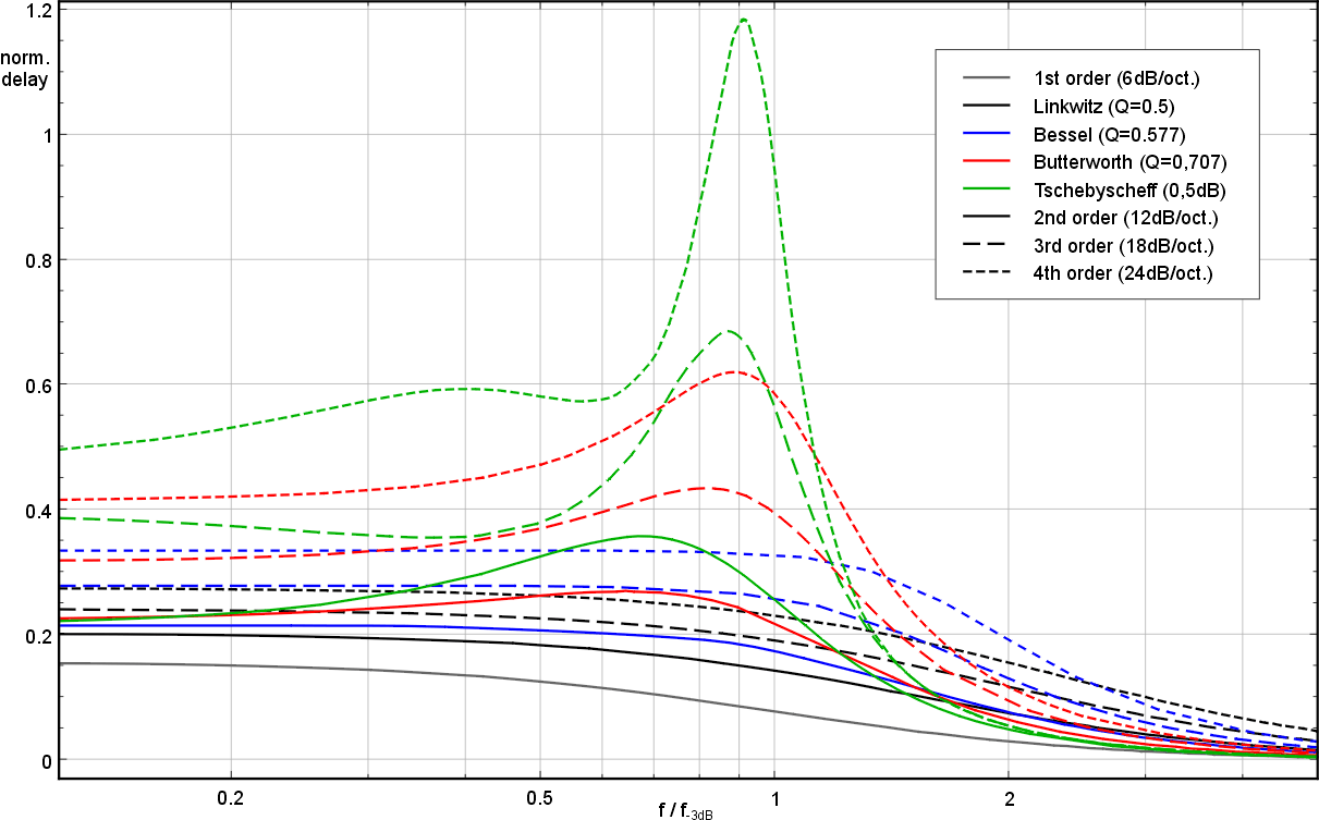
I think we should add some more information about the comparsion of different filters (analog or IIR). The short graph at the introduction gives only a view information about the most common L-R and butterworth filters. I think about something like
- http://www.maazl.de/electronic/LS/images/lowpass-response.png - Amplitude response of different lowpass-filters and
- http://www.maazl.de/electronic/LS/images/lowpass-delay.png - normalized group delay of the filters. The real group delay is the value from the graph divided by the crossover frequency (exactly the -3dB frequency).
Of course, even more information should be supplied, especially about filter matching (Phase, Amplitude, Power). This part is related to the above discussion about the relation of drivers and crossovers.
I think this article is the right place for informations like these. If there is nothing to be said against it, I would start to add some information about different low and high pass filters. If it grows too much it might be separated in it's own page. (Marcel Müller) —Preceding unsigned comment added by Marcel Müller (talk • contribs) 10:37, 14 September 2007 (UTC)
Tweaks[edit]
Posting explanations of the tweaks here...
"Networks are not only frequency specific, but also impedance specific."
yes
"Passive crossovers are not generally interchangeable between different speaker systems."
not true. If you want the best possible performance, the whole speaker system will be designed together. However generic crossovers still give good performance, and I've used many of them. Millions of generic crossovers have been made and sold, and plenty of people listen to the results happily enough.
"at high voltage and current levels."
usually high current only, high voltage speakers using crossovers are somewhat the exception, so changed phrasing.
I removed the statement that crossover noise was only amplified in some cases, as it inevitably always is. There is no way to avoid that. As for noise figure (and any other specs) sometimes being unacceptable, surely thats true for all audio system specs, and I would think everyone and their dog knows that, its why there are (consumer) audio systems on the market with widely varying specs and prices.
"Generally, active crossovers require use of tweeter protection (typically a small capacitor) since the tweeter is now directly connected to an amplifier and may be damaged due to DC in that output, or a short thump produced when an amplifier turns on or off."
This one's a bit more complex. Caps are often used but not for the above reasons.
Tweeters require protection against dc no more or less than other speaker drivers. Biamping actually reduces the risk of tweeter frying from a faulty amp, since a 10w tweeter on a 10w amp is less susceptible than the same tweeter on a 50w amp.
Thump is low frequency, and the crossover hf channel will reject it due to its frequency content. There is no more than trivial high frequency content in power-up conditions; if there were, end users would find the experience very unpleasant and consistently reject the equipment as faulty. If you've ever experienced a bad amp design that does hit the tweeter with large amplitude hf during start up you'll know what I mean!
The use of a series cap is primarily a question of amplifier design, many amps use them, many dont. A relatively small cap on the tweeter is a simple way to knock out hum and cut s/n figure by wiping out out of band noise.
"reduction in power amplifier cost and output requirement."
Use of 2 amps, one of which is of nearly as much power as the single amp would be, does not reduce cost, quite the opposite. This is precisely why its not popular. If it reduced costs, all mass market manufacturers would be biamping.
"while the whizzer, which is directly coupled to the voice coil, responds only to the rapid movements of the coil at higher frequencies."
The whizzer is hard coupled to the coil, thus it unavoidably responds to all frequencies the speaker handles. Useful output only occurs at higher frequencies, not because the whizzer doesnt respond, but because its small diameter makes its lf output of relatively low amplitude. (For a given spl a lf requires a much larger diaphragm than hf)
"argue that a single diaphragm that must produce both low and high frequencies does neither justice. "
Since around 99.9% of hifi speaker cabs avoid the inherently cheaper full range unit approach, it seems there are almost no designers that would diagree with this view. IOW its more accepted than POV, those that vote for full range units are a tiny fringe only, and not any part of mainstream design. Tabby (talk) 19:40, 17 January 2008 (UTC)
Components: fact or marketing[edit]
I've moved this here for discussion as its not really scientificaly valid, tho some do claim it as fact:
"For instance, use of non inductive resistors and special capacitor components adds significant cost, although they have some sonic benefits."
The inductance of wirewound Rs used in crossovers is truly miniscule:
- bear in mind such Rs are always counterwound to wipe almost all trace of inductance measurable at audio frequencies
- compared to the inductance tolerances elsewhere in the crossover, any R inductance is a non-event.
...Yes and no. Non-inductive resistors are usually of the CERMET type and thus offer very low noise and thermal stability. This was very relevant in the era of carbon and carbon film resistors (some of which were meander resistors with carbon film on them). But current SMD resistors are rare metal film types, so, if you don't need the power rating, any SMD resistor will do.
Re special capacitors, again there really is no science that shows any improvement for 'special' cap types. Yes one can go wrong, but small caps across long life electrolytics is about as good as one can get, and neither is a special component.
...yes and no. In the critical parts of any amplifier, a PS (polystyrene capacitor) was specified, as other types at that era had significantly higher dielectric absorption, which lead to hysteresis, and thus higher THD. Today, you can pick up inexpensive (relatively inexpensive, that is!) polypropylene capacitors of several types (metal film, foil film/foil) which have excellent dielectric characteristics and are used in critical parts of A/D samplers, timing, measuring, instrumentation and of course, audio.
Widespread shortage of technical knowledge and marketing spin makes a ready market for components with tall tale marketing spiel. ...yes, there are some unbelieveable stories out there, like folks selling "capacitor" to audiophiles who did not know that capacitor is the same as a condenser (local name). But in the area of precision electronics, precision components are and will be costly. It all depends on what the desired outcome should be and what the limiting components for such design are. But then, if you are looking for expensive components and can't mathematically reason why you need this or that, you are not likely fit to be the one doing the component selection anyway.
The one area in passive crossovers where component quality is significant is with inductors, not Cs or Rs. Tabby (talk) 06:47, 21 January 2008 (UTC)
Capacitor only[edit]
I'm going to suggest including discussion of the single capacitor passive speaker filter. Although its not a crossover on its own, when combined with the falling response of the woofer you do end up with a crossover system, part electronic, part mechanical. So it does end up being part of an audio crossover, of a most basic (but popular) sort.
IMHO no discussion of passive LS crossovers is complete if it omits this very popular option. Tabby (talk) 06:57, 21 January 2008 (UTC)
- I agree, but I think it should go further to include the inductor, too. Simple crossovers marketed by Radio Shack and others in the 1970s, and perhaps later, were composed of a capacitor (to increase the impedance to the tweeter as frequencies declined) and a coil (to increase the impedance to the woofer as they rose). Anoneditor (talk) 17:33, 21 January 2008 (UTC)
Filter comparison graph with no reference[edit]
The graph comparing filters in the overview has multiple strange errors. It looks more like marketing speak than physics. 1. it incorrectly states that summing a low and a high Butterworth filter has a peak at the crossover frequency. Define -6dB as the cutoff frequency for a Butterworth, and you have a "flat" crossover response. You can get a dip, peak or flat depending on your definition. 2. The crossover freq is strangely given as 1 rad/s, not Hz, and gives an unrealistic crossover freq of 0.16Hz. 3. Neither a Butterworth, nor an LR filter is has a perfectly straight 0dB response as indicated in the graph.
Can anyone help clarify this? Should this graphic be corrected or removed? —Preceding unsigned comment added by 213.153.22.143 (talk) 23:03, 18 January 2010 (UTC)
- 1. Cutoffs
- The graph is correct in its calculations, but it only depicts the case where the cutoff frequencies are the same. While one can spread the frequencies in a 2nd order butterworth crossover to get a flatter sum, it will have some ripple near the crossover. You cannot arbitrarily call the cutoff for a butterworth as the -6dB point because by definition the cutoff is the point where the L and C in the crossover resonate, which occurs at -3dB in a butterworth filter.
- 2. Units
- I never noticed the units before - it appeared to me to be a normalized frequency graph, omega/omega_c (omega_c being the cutoff or resonant frequency) which is by definition unitless. Normalized frequency graphs are a common way to represent filters, as their response shape is the same no matter what frequency they are at. The graph should be corrected.
- 3. The response shapes in the graph are correct. Second order, or 2 pole circuits have a 40dB/decade slope and a Butterworth is -3dB at cutoff and an LR is -6dB. The sum of a lowpass and highpass butterworth 2nd order crossover has a peak if their cutoff frequencies are the same. A Linkwitz-Riley 2nd order is -6dB at the cutoff and sums flat.
- I think the graph is somewhat misleading and would be better replaced with one that shows first through 4th order sums - butterworth for odd order and LR for even, which all sum flat.--Ron E (talk) 16:19, 23 January 2010 (UTC)
Fans of the first order[edit]
It says, 'First-order filters are considered by many audiophiles to be ideal for crossovers.'
Based on my experience, that opinion about opinions is quite dubious. Maybe I do not hang out in the same net.circles that whoever wrote it does, but I have never once read the opinion that a first order filter is desirable for any reason other than cost. One reason steeper cutoff slopes are preferred in high-pass stages is that if a driver does not "need" to pass a given low frequency, it shouldn't. Low frequencies are to be terminated with extreme prejudice. The "unneeded" low frequencies contribute to Doppler distortion. I do know from experience that Doppler distortion sounds nasty. Based on the net surfing I've done, and I have done a lot of it, both the techies and the golden-ears prefer 4th order Linkwitz-Riley, which has 24db/8va rolloff and polite phase characteristics. Jive Dadson (talk) 01:32, 16 December 2010 (UTC)
- In practice, I agree that 4th-order filters are often best suited to crossover duties. There are, however, other opinions. People who don't like higher-order filters complain about ringing and about insertion loss (if the crossover is passive loudspeaker level). First-order filters have more amp power delivered and less phase shift according to proponents. Some first-order products include Meadowlark Kestrels, Bowers & Wilkins Nautilus, and (I think) everything from Thiel Audio. Roy Johnson from Green Mountain Audio wrote a white paper about [ better sound results from first-order crossovers.]
- Of course, idealism with regard to loudspeaker crossovers is a hopeless goal. The loudspeaker drivers have their own innate frequency response which tapers off in the manner of a crossover filter, and the enclosure plays a huge part in how the driver responds. You should not decide what crossover to use without acknowledging the rolloff characteristics of the enclosure/driver combination. The whole system of enclosure/drivers/crossover should be engineered with the goal of suitable sound output. Binksternet (talk) 02:16, 16 December 2010 (UTC)
- I did not intend to debate the opinion, although I think I could hold my own. I just wanted to point out that it is an opinion, and does not belong in a Wikipedia article without citation, and expert rebuttal if such exists. The same can be said for the knock on full-range drivers. It reminds me of interviews on certain cable news channels in the US. The interviewer challenges the interviewee with an assertion like, "Some say your policy is akin to biting the heads off of kittens..." The technique has been called "some-say" journalism. (Some say it is "some-say" journalism?) Audiophiles and DIY'ers can have an irrational and emotional attachment to their chosen methods, akin to devotion to a sports team. Un-cited criticism here seems unnecessarily provocative. Okay. Full disclosure. I built a system that uses full-range drivers (Jordan Jx92s) augmented by a subwoofer coupled with a fourth order crossover (Linkwitz-Riley). Some say it is as good as any system they have ever heard in a moderate size room, regardless of cost. (I am one of them.) Hence, irk. Root, root, root for the home team. Jive Dadson (talk) 22:49, 16 December 2010 (UTC)
External links modified[edit]
Hello fellow Wikipedians,
I have just modified 3 external links on Audio crossover. Please take a moment to review my edit. If you have any questions, or need the bot to ignore the links, or the page altogether, please visit this simple FaQ for additional information. I made the following changes:
- Added
{{dead link}}tag to http://www.rane.com/pdf/ranenotes/Linkwitz%20Riley%20Crossovers%20Primer.pdf - Added archive https://web.archive.org/web/20070704013822/http://www.ksdigital.de:80/english/index.html to http://ksdigital.de/english/index.html
- Added archive https://web.archive.org/web/20060901190700/http://www.ipl.iit.edu/IPL_papers/SP99.PDF to http://www.ipl.iit.edu/IPL_papers/SP99.PDF
- Added archive https://web.archive.org/web/20090204130232/http://fullrangedriver.com:80/singledriver/theory.html to http://fullrangedriver.com/singledriver/theory.html
When you have finished reviewing my changes, please set the checked parameter below to true or failed to let others know (documentation at {{Sourcecheck}}).
This message was posted before February 2018. After February 2018, "External links modified" talk page sections are no longer generated or monitored by InternetArchiveBot. No special action is required regarding these talk page notices, other than regular verification using the archive tool instructions below. Editors have permission to delete these "External links modified" talk page sections if they want to de-clutter talk pages, but see the RfC before doing mass systematic removals. This message is updated dynamically through the template {{source check}} (last update: 18 January 2022).
- If you have discovered URLs which were erroneously considered dead by the bot, you can report them with this tool.
- If you found an error with any archives or the URLs themselves, you can fix them with this tool.
Cheers.—InternetArchiveBot (Report bug) 07:58, 21 October 2016 (UTC)
More External Links corrected from sound.whsites.net to sound-au.com On 20211211 by W1LL1Ed1T
- Article about active crossovers
- Comparison of active and passive crossovers
- Comparison of series and parallel crossovers
- Description of a L-R crossover
- [http://sound-au.com/lr-passive.htm — Preceding unsigned comment added by W1LL1Ed1T (talk • contribs) 17:16, 11 December 2021 (UTC)
Former ELs, potential refs[edit]
Discospinster removed the External links section which may be appropriate. The sources may be useful as additional references. I reproduce the content here in case I or another editor is able to make use of them. ~Kvng (talk) 13:13, 14 December 2021 (UTC)
- Lenard Education on crossovers illustrated overview of audio crossovers.
- diyAudioAndVideo.com – DIY Audio site with information on building crossovers. Includes a crossover calculator for 15 different types of crossovers.
- KS Digital – makers of several loudspeakers with digital crossovers
- Article about active crossovers
- Comparison of active and passive crossovers
- Comparison of series and parallel crossovers
- Description of a L-R crossover
- Passive crossover design article
- Linkwitz Lab Crossovers
- Linkwitz-Riley Crossovers: A Primer
- Design of Digital Linear Phase FIR Crossover Systems
- Full-range Driver & Loudspeaker Theory
- Audioholics.com Filter & Crossover Types
- A Bessel Filter Crossover, and Its Relation to Others
- Active Low-Pass Filter Design